
Circuit Diagram Of Xor Gate
Logic Gates XOR and XNOR in PLC Programming | PLC Tutorial for Beginners - YouTube In this video, learn Logic Gates XOR and XNOR in PLC Programming | PLC Tutorial for Beginners. Find.
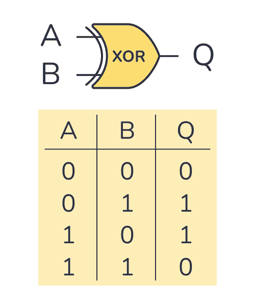
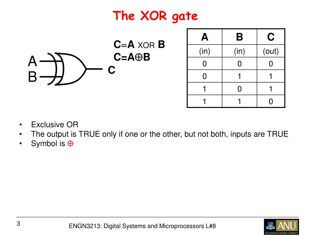
XOR Gate Logic Gates Tutorial
1. AND logic function Figure 1a shows a situation where an output is not energized unless two, normally open, switches are both closed. Switch A and switch B have both to be closed, which thus gives an AND logic situation. We can think of this as representing a control system with two inputs A and B (Figure 1b).
PLC Logic Functions PLC Ladder Logic Gates PLC Commands
Published May 27, 2021 Logic gate: a cool term, but what does it mean? This article will introduce the concept of a logic gate as well as describe how each specific logic gate (OR, AND, XOR, NOR, NAND, XNOR, and NOT) works. Readers like you help support How-To Geek.

Siemens PLC XOR , XNOR In The LOGO! Logic Gates YouTube
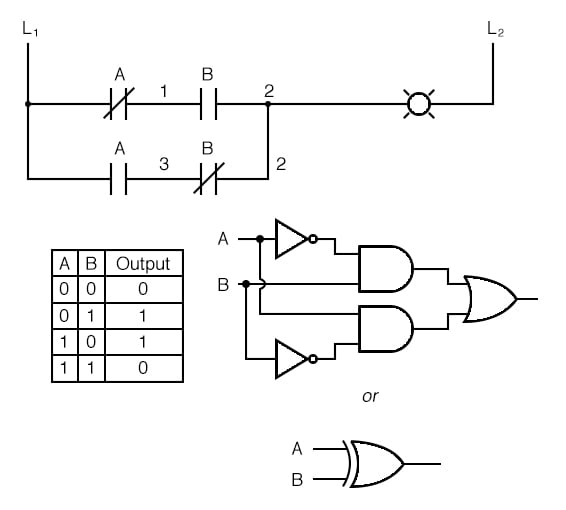
The symbol for the XOR gate is shown by added a curved line to the OR gate symbol. The ladder logic to implement an XOR gate is a little more complex then the others. How useful is the XOR logic? You probably use the XOR gate everyday without thinking about it if you have a room with a light that works off two switches.. In the PLC program.
Xor Ladder Logic Diagram Wiring Diagram Schemas
In this video, we learn the logic gates AND, OR, NOT, XOR, NAND, NOR, XNOR functions and truth tables using PLC programming.*** Industrial Automation Tutoria.

Logic Gates XOR and XNOR in PLC Programming PLC Tutorial for Beginners YouTube
PLC Ladder Logic of OR Gate 3. NOT Gate NOT logic gate is the inverse logic gate. When the input is ON, the output will be OFF and when the input is OFF, the output will be ON. NOT Gate: Y = (!A) The below figure shows the PLC ladder logic conversion of NOT gate, which shows the output works exactly opposite of the input.
Xor gate
Logic Gates in PLC Ladder Logic. We can construct simply logic functions for our hypothetical lamp circuit, using multiple contacts, and document these circuits quite easily and understandably with additional rungs to our original "ladder.". If we use standard binary notation for the status of the switches and lamp (0 for unactuated or de.

CircuitVerse XOR GATE USING 3 INPUTS
In this video, we will try to understand the concept of implementing XOR gate and various boolean logic using PLC ladder programming. The implementation of these logic gates is explained.

XNOR GATE Logic programming using TWIDO SUITE PLC software YouTube
In this video, you will learn the universal logic gates in PLC programming using Siemens Tia Portal software.Here you will learn the NAND, NOR, XOR, XNOR log.

Introduction to XOR Gate projectiot123 Technology Information Website worldwide
PLC Exclusive OR (XOR) LOGIC PLC Exclusive NOR (XNOR) LOGIC PLC Logic Functions Say, for an automatic drilling machine, there might be the condition that the drill motor is to be activated when the limit switches are activated that indicate the presence of the workpiece and the drill position as being at the surface of the workpiece.

a XOR gates b (i) and (ii) XOR gate layout Download Scientific Diagram
27.5k FAQs Reviews What are NAND, NOR, and XOR gates? There are many ways to build logic gates for digital circuits. However, most of them do not use the minimum and maximum power consumption, the power consumption gap between at least two states of a logic gate, or the number of transistors.

XOR Logic Gate in PLC Ladder Diagram EXOR Logic and Truth table YouTube
Instrumentation Tools 87.1K subscribers Join Subscribe 659 views 1 month ago OpenPLC In this video, you will learn the XOR and XNOR logic gates from the PLC lab exercise. OpenPLC Software.

XOR GATE Logic programming using TWIDO SUITE PLC software YouTube
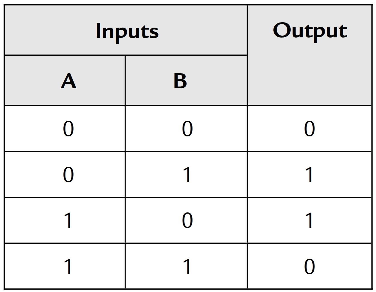
XOR Gate Symbol: XOR Gate Truth Table: XOR Gate PLC Ladder Logic Diagram: Exclusive- XNOR Gate XNOR Gate Symbol: XNOR Gate PLC Ladder Logic Diagram: Related Projects: Description:
schneider somachine xor function in Ladder. r/PLC
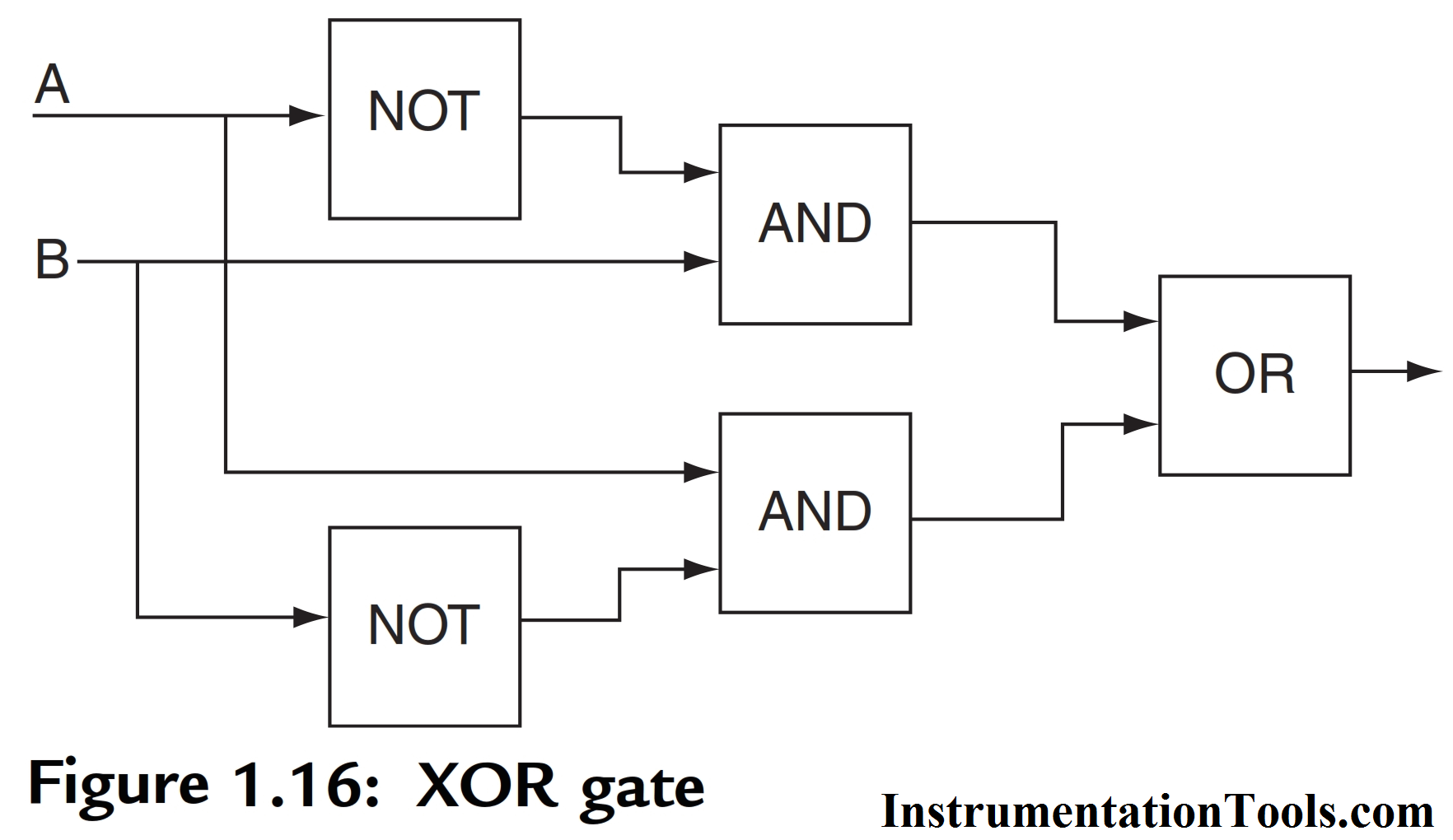
For example, we have shown in the logic gates article that, XOR can be used to compare two inputs and check if they are equal or not. On the other hand, someone may say, oh we can do XOR by using the basic three gates of "AND", "OR", and "NOT". That's correct.
(a) Traditional XOR gate constructed by six transistors (three PMOSs... Download Scientific
Technical Article PLC Programming Commands: Boolean Functions and Bit Redistribution September 15, 2022 by Jon Peterson Learn how to use the boolean bitwise functions AND, OR, XOR, and NOT in your PLC programming, as well as some instructions used to change the position of bits and bytes in your INTs and DINTs.
Xor Ladder Logic Diagram Wiring Diagram Schemas
1. NOT GATE In electronics, NOT GATE is also called an ' Inverter' or ' Buffer'. Working: NOT gate works as inversion. It takes one input and gives one output. When the input is high then the output is low and vice-versa. Logic Gate Truth Table for NOT Gate: NOT Gate in PLC programming: